Tim's XY Plotter Circuit Boards
(Current)
These are my Current Circuit boards. I made for my XY Plotter here: Tim's XY Plotter.
I changed and fix a few things. (oh and still not quite as I want)
Some details of my old boards can be found here: My Previous Circuit Boards
To see how I make my own PCB's take a look at my Blog here: Tim's PCB (Plotted Circuit Board).
I am controlling the plotter with an Arduino NANO.

Pins currently used are:
Motors
14 (A0) = Stepper Motor 2 direction
15 (A1) = Stepper Motor 2 step
16 (A2) = Stepper Motor 1 direction
17 (A3) = Stepper Motor 1 step
7 (D7) = Enable Stepper Motors.
The drivers are set to 16 micro steps
Stops
2 (D2) = Y Stop
3 (D3) = X Stop
Tools
10 (D10) = Servo 1
9 (D9) = Servo 2
5 (D5) = Tool Power, PWM, On/Off
4 (D4) = Stepper Motor Direction. Auxiliary Height Control (Z)
20 (D20) = Stepper Motor Step. Auxiliary Height Control (Z)
The Stepper Motor Drivers I am using are:
Pololu DRV8825

There are other drivers that are similar and have a compatible pin configuration.
the Pololu DRV8825 has three pins for setting the Step Mode. (if using a different driver check the order of the pins, I have found the sequence to be reversed on some)
For the Pololu DRV8825, the modes are as follows:
|
MODE2
|
MODE1
|
MODE0
|
STEP MODE
|
|
0
|
0
|
0
|
Full step (2-phase excitation) with 71% current
|
|
0
|
0
|
1
|
1/2 step (1-2 phase excitation)
|
|
0
|
1
|
0
|
1/4 step (W1-2 phase excitation)
|
|
0
|
1
|
1
|
8 microsteps/step
|
|
1
|
0
|
0
|
16 microsteps/step
|
|
1
|
0
|
1
|
32 microsteps/step
|
|
1
|
1
|
0
|
32 microsteps/step
|
|
1
|
1
|
1
|
32 microsteps/step
|

I currently have it set at 16 microsteps/step (100).
This is quite high, its pushing the Arduino NANO near to its limit for speed calculations. (I may set it back to 8 if I find it problematic)
The driver also has a small potentiometer for setting the limit on the amperage to the motors.
Video: setting the current limit on Pololu stepper motor driver carriers
The latest HEX file for my plotter is: Tims_Plotter_05.ino.with_bootloader.hex (old bootloader)
The firmware returns "ok" with carriage return and new line, on acknowledge of a command.
The commands it recognizes followed by a carriage return are:
G00 X<dec.number> Y<dec.number>
G00 F<dec.number>
G01 X<dec.number> Y<dec.number>
G02 X<dec.number> Y<dec.number> I<dec.number> J<dec.number>
G03 X<dec.number> Y<dec.number> I<dec.number> J<dec.number>
G04 P<number>
G90
uses
M03 L<number> as on/down (optional level)
M05 L<number> as off/up (optional level)
M18 motors of
M100 help
R01 as reset to home
The reason I am not using an off the shelf grbl shield. (one could be used with different pin configuration in the firmware)
Is because I want to use the standard (Arduino) interrupt pins.
The reason for wanting the interrupt pins is: Future versions may detect out of bounds moment.
My latest software to send plot files can be found here: Tim's XY Stepper Controller
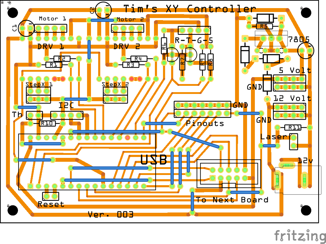
So the first board is the Controller board. (My current Board)
I have managed to get the latest iteration of my board to a size of 100mm 70mm.
This size of board are quite cheep to buy on eBay.

Getting it to fit on the 100x70mm board, I have not left the USB easily accessible, this is not a problem, as I will be connecting to it via Bluetooth.
I made some extensions on my 3D Printer to support it to the existing brackets.


STL Files:
Mount_L.stl
Mount_R.stl
Main changes to the board:
The new board has a 7805 for powering 5v rail.
The 5 volt and 12 volt pinouts are now better placed.
Added Bluetooth Module Socket.
Added I2C Socket.
Added a clone pinout for my Laser, so it can be left plugged in.

Some of the remaining pins not used by the motors and stops are accessible via Pinouts.
I have created the circuit with fitzing, here is the file: Tim's XY Controller (100x70).fzz


To get every thing to fit the 100mm X 70mm Board I was limited to where the components would go.
There is a slight issue when plugging in a USB cable to the Arduino NANO, the cable to the second board needs to be removed.
This is not much of an issue as I will be using Bluetooth to communicate with the plotter, USB is only needed to program the board.
From The controller board there are two 4 core cables running down to the stepper motors, one left and one right. (800mm approx.)
One 8 core cable drops down to the Second Board.(450mm approx.)

The Second board has an optical sensor for the Y Axis Stop, Pinouts from the cable and an other socket for the cable to continue to the Trolley.

On top of the board is fixed a Shutter for the Y Axis Optical Sensor.

STL File:
New X Stop.stl
One Printed the end of the stop needs to be coated with something that won't let Infrared Light through.
I use a black permanent marker.

I have done a video to show that this is necessary when I was modifying my 3D Printer.


From this board, the cable continues on to the Trolley.(approx. 400mm)

The Cable is supported at the mid point.
The next board has an Optical Sensor for the X Axis Stop. It also has Pinouts from the cable, some of which are placed in printed sockets for the Servo Plugs.

I have updated the sockets on the parts post.
I have created the circuit with fitzing, here is the file: Circuit Board Trolley 003.fzz


I have a web site as well:
Tim's Place Mirror:
Tim's Place
No comments:
Post a Comment