There are two main types of Bluetooth Modules the 6 pin HC-05 and the 4 pin HC-06


When fitted it only uses the middle 4 pins.
To configure a Bluetooth Module requires communicating with the device using "AT" Commands.
Not all manufacturers use the same commands, they use similar commands with slight differences.
I have seen many versions of Bluetooth Modules on the market, 4 pin, 6 pin, HC-05, HC-06 and HC-10.
So downloading the right data sheet and manual is essential.
This information refers to the two above. (If I get any of the other types of modules I will update this to suit)
Bluetooth Modules have 2 main communication modes:
1. Data mode.
Where data is just sent and received.
2. Command mode.
In Command mode, "AT" commands can be sent to the device, to make it do tasks.
The HC-05 6 pin Module needs the CMD pin High or Low to set the mode. (The breakout board usually has a button)
The HC-06 4 pin module automatically changes to Data Mode when connected to a Paired Device and to Command Mode when not connected to a Paired Device.
I have one of these which I use to configure my Bluetooth Modules, I like because it has jumper to select Logic Level Voltage. Which means I can connect the Bluetooth Module direct.
 eBay Search USB to UART If you have one of these, you could use it instead of using an Arduino UNO.
I will show how to do it with USB to UART Device after I show how to do it with an Arduino.
WARNING
Not all Bluetooth Modules can accept a 5 volt data line.
Although a Bluetooth Module may be advertised as 5 volt compatible, this may ONLY refer to the Power Input. The Data connections (RXD and TXD) may only be 3.3 volt.
Putting 5 volt on the RXD pin will destroy that input pin on the UART chip.

So, because the Arduino UNO has 5 Volt data pins, some form of voltage reduction is required.
You can use resistors to make voltage dividers on each data line, but I prefer to use MOFETS.
You can buy a Logic Level Converter on eBay.

This is a board I have made and use for other projects.
Here is a breadboard Circuit using the Logic Level converter bought on line to make things simple.

The circuit:


The Bluetooth devices UART speed are set to 9600 by default in Data Mode.
So, using the sketch above in data mode, may need the BTS.begin(38400) changing to BTS.begin(9600). (or if you have changed the UART speed, to what ever you have changed it to.)
When in Command Mode, Commands may be able to be sent at 38400. (depends on how command mode was set.)
I change 2 things: The device name and the device UART speed.
The Name of the device I will be changing this one to: "Tim's Plotter". (it can be whatever you want)
This is the name you see when pairing the Bluetooth device.
The speed is dependant on how it is connected.
There is a limit if it is connected to soft serial, this is: 57600bps.This is how it is connected above. (Soft Serial)
However, on my Plotter Controller, I am going to connect it to pins 0 and 1, hard serial (the serial chip). The same pins the USB uses, which I set at 115200 when using the USB to communicate with the plotter.
So at the end of the day I will be setting the speed of the Bluetooth Device UART to 115200.
This means that once the speed is set, any other changes may need a USB to UART Device to communicate with it, the above may not work.
Check it is working first.
My Bluetooth Device has a red LED that flashes quite rapidly in data mode, waiting to connect.
Pair the device with your computer. It's default name will be something like HC-05.
The Password will probably be: 1234 (HC-06) or 000000 (HC-05)
After you have paired the device with your computer, you should be able to see it listed in the com. ports in the Arduino IDE.
You don't want the Bluetooth device connected to another Paired Device when setting it to Command mode.
When in command mode communication will be through the USB connected to the Arduino UNO, with the above sketch installed.
Command mode (HC-05) is set with the CMD pin (pin 34).
The module I have has a button connected to this pin.
With the CMD pin pulled to logic level 0, or left open. The Bluetooth Device will start in Data Mode.
By setting the CMD pin to Logic High. The Bluetooth Device is set to Command Mode.
Command Mode can be set in two ways:
While powering up. (The UART is set to 38400bps, 8 data bits, 1 stop bit, no parity, no handshake)
After powering up. (The UART is set to what ever it was set to using the AT+UART Command)
(The HC-06 module automatically changes to Data Mode when connected to a Paired Device and to Command Mode when not connected to a Paired Device.)
The "AT" commands for the HC-05 and HC-06 are similar but have slight differences.
So I will put HC-05 in Bold and (HC-06 in Italic) in brackets.
The AT+UART (AT+BAUD) Command is what will be used to set the Data UART speed to 115200.
What I do for the HC-05, is have it all powered up as shown above and unplug the Bluetooth Device from the Breadboard, then holding the button pushed in on the Bluetooth Device, plug it back into the Breadboard.
When plugged in and the LED lights up I let go of the button. The LED now flashes at a slow rate.
Because the CMD pin was Logic High when powering up the UART should be set to 38400.
In Arduino IDE, set the Com Port to whatever the Arduino UNO is connected to.
Now to open the Serial Monitor from the Tools Menu in the Arduino IDE.

Set the baud to 38400 in the Serial Monitor.
Make sure "Both NL & CR" are set. (All commands must end with Carriage Return and Line Feed)

"AT" commands can now be sent.
To make sure all is OK, type AT (AT ) and click Send.

After the Send Button is pressed, OK should be returned in the output window.

If the Bluetooth Device returns OK, then all is good.
Now commands can be sent to change the settings.
Name:
To check the current name type: AT+NAME? (AT+NAME)
To set the name type: AT+NAME=Tim's Plotter (AT+NAMETim's Plotter) (can be any thing after the equals sign (no equal sign), up to 31 characters)
Type: AT+NAME? (AT+NAME) again to check all is OK.

UART speed (BAUD):
There is a big difference in setting the UART speed on each version of the devices.
To check the current UART speed: AT+UART? (AT+BAUD)
HC-05 may return a different speed than the one set in the Serial Monitor, this is OK, the speed currently connected at is the safety speed at boot up, that is, if Command Mode is initiated at boot, the speed will always be 38400 so it can be reset.
Also:
HC-05 returns: Baud, Stop Bit Code, Parity Code
HC-06 returns: Baud Code
So:
HC-05
baud = any one of the following:
4800
9600 (default)
19200
38400
57600
115200
234000
460800
921600
1382400
Stop Bit Code = one of the following:
0 = 1 bit (default)
1 = 2 bits
Parity Code = one of the following:
0 = None (default)
1 = Odd parity
2 = Even Parity
HC-06
Baud Code = one of the following:
1 = 1200
2 = 2400
3 = 4800
4 = 9600
5 = 19200
6 = 38400
7 = 57600
8 = 115200
9 = 230400
To set the UART to what my controller will be using to communicate with the Bluetooth Device,
type: AT+UART=115200,0,0 {baud, stop code, parity code} (AT+BAUD{baud code})Type: AT+UART? (AT+BAUD) again to check all is OK.

From here on in Data Mode, communication can only be done at 115200.
Also HC-06 Command Mode.
If ever the Bluetooth Device (HC-05) UART needs changing to a lower speed to be used on Soft Serial, it can be connected at 38400, if booted with CMD pin set High at boot time.
To query the Password, the command is: AT+PSWD? (AT+PIN)
If the Password needs changing, the command is: AT+PSWD=1234 (AT+PIN000000) (replace numbers with alphanumeric password 16 characters max)
The Bluetooth device is ready to be plugged into the Plotter Controller Board.
Using and connecting the Bluetooth Module to the PC with a USB to UART device is much easier.

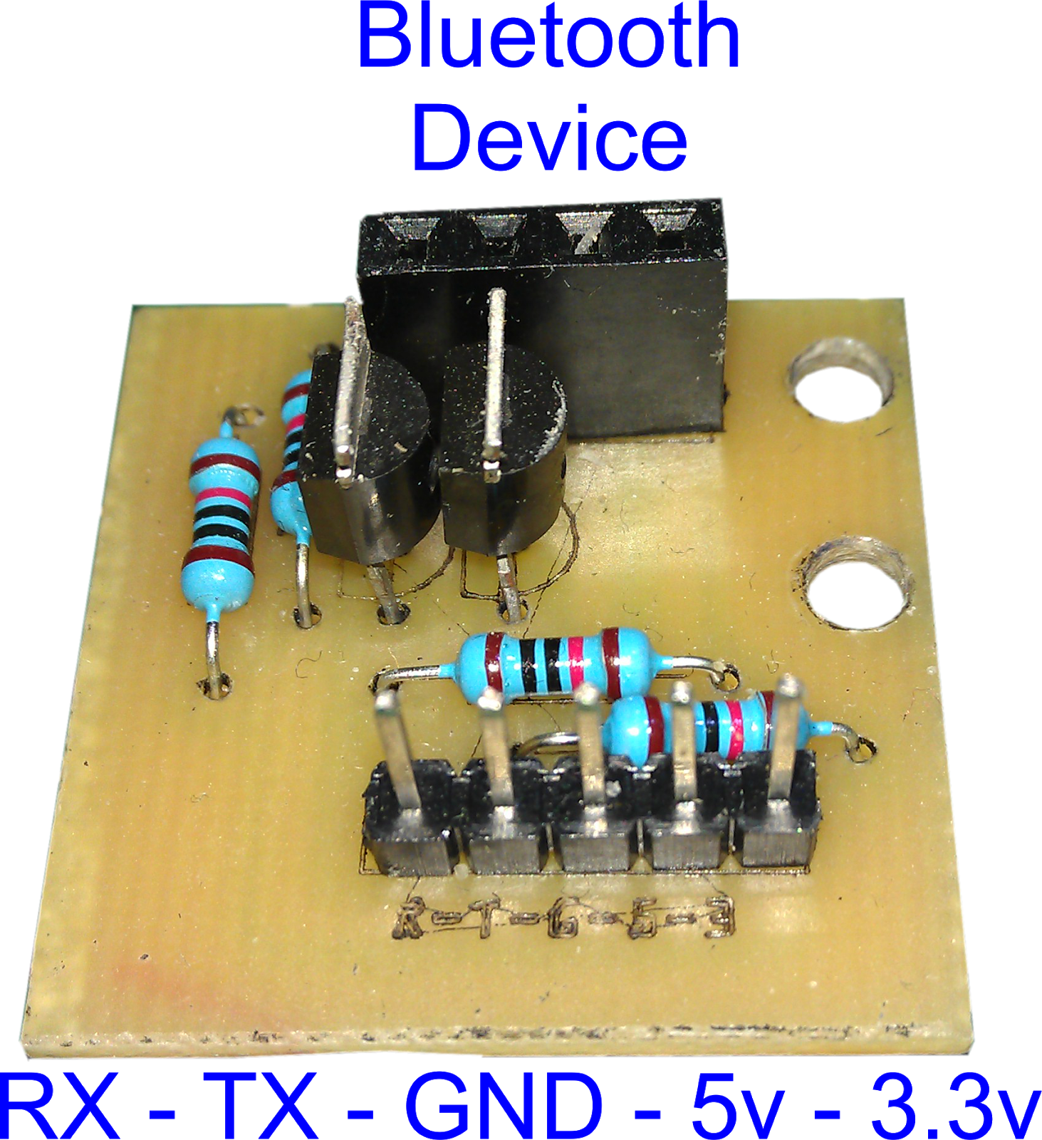
To connect the two devices, I used two Socket headers (an X5 and a X4 header) soldered together with the outer pins joined with a wire.
NOTE! The jumper is set to 3.3volt. (this is the data voltage)
The circuit:

Instead of using the serial monitor in the Arduino IDE, I have made my own Serial Monitor application.
Tim's Serial Monitor.

Using this Serial Monitor, I connect just as I did with the Arduino IDE Serial Monitor.
It has some pre-sets that you can change to what ever you like, it makes it quicker than typing most used phrases over and over again.
Also I have added notes about Bluetooth, The Notes can be edited to what ever.
The plot plots Numeric data received.

My Serial Plotter does not draw data very fast, so if data is received too quickly, it is placed in the serial ports buffer and plotted as soon as my application can plot it. (not expert as programming)
Finding which COM Port is attached to which Bluetooth Device in Window 10.
Open the Settings window and chose Devices (Bluetooth, printers, mouse).

2. Click the COM Ports tab in the new Bluetooth Settings window.
You should see all the Bluetooth devices that have been paired with your computer.
Each Bluetooth device has two COM Ports allocated to it.
One for incoming data and one for outgoing data.
When selecting a COM Port to a device in software, you normally chose the Outgoing COM Port.
This comment has been removed by a blog administrator.
ReplyDelete